Introduction
This is a the third part in a four part series (Part 1, 2a, 2b) on my research into the extension and development of lp-CMFD. This post assumes that the reader has been following so far on how lp-CMFD works (see this section) and how it can be applied to 1D geometry (see this section). This post is a summary of the following article: “Implementation and performance study of lpCMFD acceleration method for multi-energy group k-eigenvalue neutron transport problem in hexagonal geometry” which was published in Annals of Nuclear Energy in 2020.
lp-CMFD and geometry
1D geometry
The modification of CMFD with “linear prolongation” is essentially the integration of geometric information to give better estimates of the flux updates. This allows us to have fine mesh updates which are continuous across the coarse mesh boundaries. For 1D geometries, we first calculate the update value at coarse mesh boundaries then linearly interpolate the internal fine mesh values between the two boundary values.
2D rectangular geometry
For 2D rectangular geometry, we extend the geometric interpolation further so that we now calculate the internal values by using bilinear interpolation on the 4 corner values. E.g. Consider the following 3×3 coarse mesh grid with a central coarse mesh with index $I,J$.
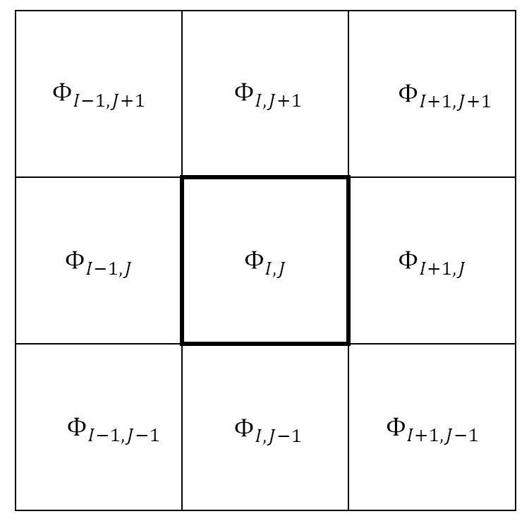
The $\delta \Phi_{TL}$ top left (TL) vertex of this grid is defined as
$$
\delta \Phi_{TL} = \frac{1}{4}( \delta \Phi_{I-1,J+1} + \delta \Phi_{I,J+1} + \delta \Phi_{I-1,J} + \delta \Phi_{I,J}),
$$
The vertex values of $\delta \Phi$ at the top right (TR), bottom left (BR) and bottom right (BR).
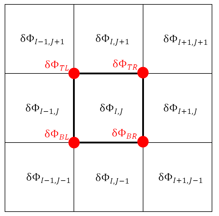
It is easy to see that we can use these 4 vertices to perform bilinear interpolation and obtain an interpolated value of $\delta \Phi$ at any point in the interior of the rectangle.
2D unstructured meshes
The generalization to any 2D mesh with convex geometry with an arbitrary number of vertices requires more mathematics. Fortunately, the development of an interior interpolation system is already well known: the Barycentric coordinate system. This system effectively transforms the coordinate system ($x,y$) into another system where the number of coordinates is equal to the number of vertices inside the mesh ($\lambda_{1}, \lambda_{2},…\lambda_{K}$). Using this coordinate system, any interior quantity is calculated as:
$$
\delta(x,y) = \sum_{k}^{K} \lambda_{k}(x,y,)\delta_{k},
$$
where $\delta_{k}$ is the update value at the vertex and $\lambda_{k}$ can be thought of as a weighting factor from every vertex to an interior point ($x,y$) inside the mesh. When the fine mesh center is close to vertex $k$, then $\lambda_{k} \approx 1$.
The derivation of the Barycentric coordinate system is outside the scope of this post and I will remark only on the mathematical steps for lp-CMFD application.
First, we determine the value of $\delta$ at the vertex by angle-weighting the coarse meshes which surround the vertex.
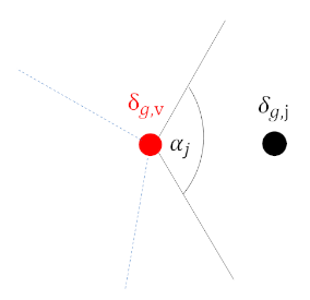
Meshes which sweep out larger angles at the vertex have more contribution to the $\delta$ value at the vertex.
We next use the Barycentric method by Meyer et al1, which we chose due to its ease of implementation and smoothness within the coarse mesh. Using the following figure …
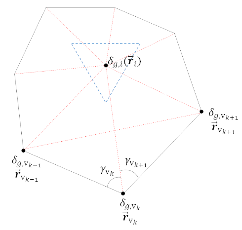
… we calculate the fine mesh update $\delta_{i}$ with fine mesh center coordinates ($\vec{\boldsymbol{r}}_{i}$) as
$$
\lambda_{k} =
\frac{\text{Area}(r_{v_{k-1}}, r_{v_{k}}, r_{v_{k+1}}) }{\text{Area}(r_{v_{k-1}}, r_{v_{k}}, r_{i}) \times \text{Area}(r_{i}, r_{v_{k}}, r_{v_{k+1}})}
$$
with some simplification, we have
$$
\lambda_{k} = \frac{ \text{cot}(\gamma_{v_{k}}) + \text{cot}(\gamma_{v_{k+1}}) }{|| r_{i} – r_{v_{k}}||^{2}}
$$
and finally
$$
\delta_{i} = \frac{\sum_{k} \lambda_{k}\delta_{k}} {\sum_{k} \lambda_{k}}
$$
Moving on to some numerical tests
We tested the Barycentric formulation of lp-CMFD on a hexagonal grid for two multi-group neutron transport problems2. In this post I will only show the the second of these problems since it has a more realistic hexagonal reactor assembly geometry.
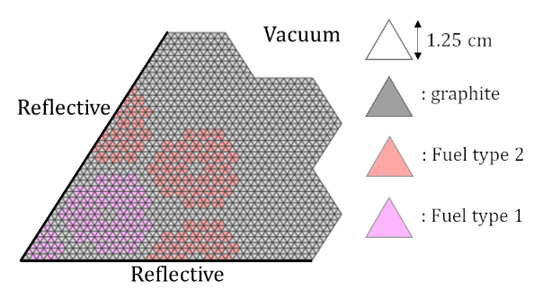
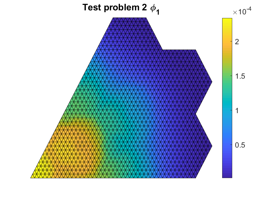
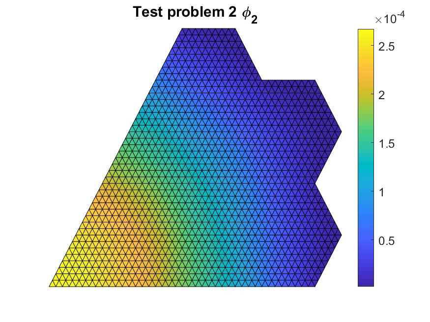
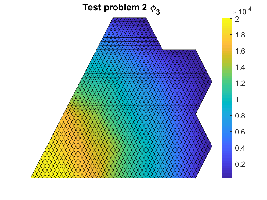
We started by validating that our code was implemented correctly with flux values that were close to the literature reference values. The figures below show the multi-group scalar flux solutions.
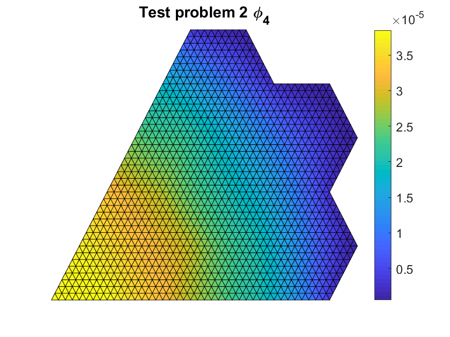
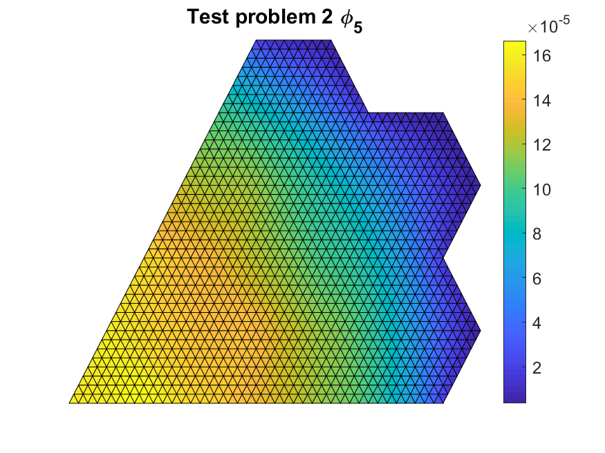
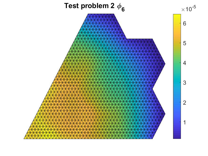
We tested different coarse mesh overlays. In terms of increasing coarse mesh size, we have $P_{CM}=4$ having 4 fine meshes per side, $P_{CM}=8$ having 8 fine meshes per side and a mixed hexagonal-triangular coarse mesh grid. The last grid overlay treats each assembly as a coarse mesh.
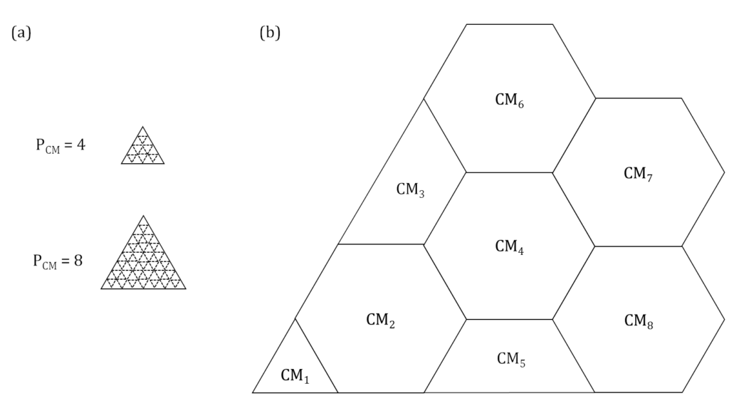
(a) Equilateral triangle coarse mesh grid (dotted lines represent interior fine mesh boundaries); (b) Mixed hexagonal-triangular coarse mesh grid (interior fine mesh boundary not shown)
Numerical performance and stability analysis of CMFD vs lp-CMFD
The first show the results of $P_{CM}=4$ and $P_{CM}=8$
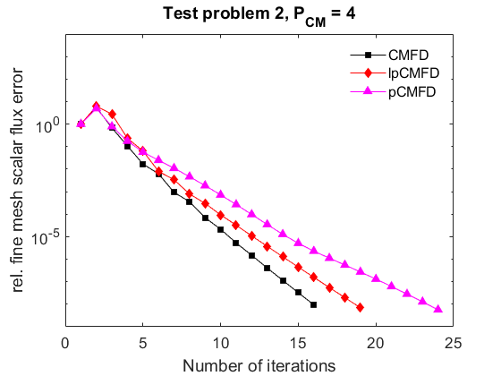
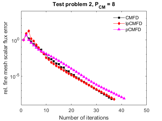
The results show that CMFD is able to converge and has better relative performance to lp-CMFD when the coarse meshes are small.
Now for the results for the mixed triangle-hexagonal grid
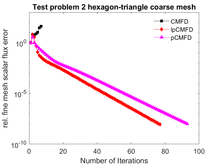
When used on the grid with the largest coarse meshes, CMFD diverges whereas lp-CMFD is able to converge. We should note that increasing the size of the coarse meshes severely reduces the effectiveness of CMFD acceleration, regardless of which variant is used.
Despite the reduction of effectiveness, the use of CMFD acceleration is still much faster than the not using acceleration at all for this large coarse mesh grid as shown below
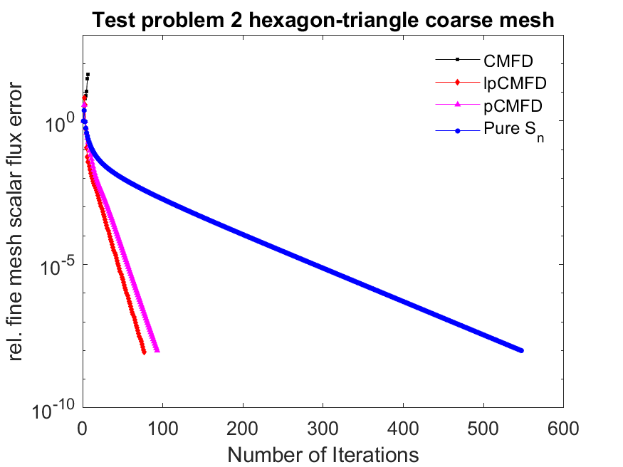
The blue line shows that it took around 550 iterations without any acceleration compared to 80 iterations for lp-CMFD (a reduction of about 85%). The extra computational cost of lp-CMFD is much less than the transport sweep calculations.
In summary …
lp-CMFD uses geometric information to update the source terms of the fine mesh cells compared to the flat-flux updates for the conventional CMFD method. The geometric interpolation is easy to do in 1D or 2D rectangular geometry. However more involved methods are needed when the coarse mesh cells are composed of irregular convex polygons. In this work we investigated the use of Barycentric coordinate systems for the basis of interpolation. We showed that lp-CMFD could be implemented effectively and was stable when the coarse mesh size was increased unlike CMFD.
Footnotes
